Big Data – Lambda or Kappa Architecture?
Big Data Analytics stands apart from conventional data processing in its fundamental nature. In the realm of Big Data, there are two prominent architectural concepts that perplex companies embarking on the construction or restructuring of their Big Data platform: Lambda architecture or Kappa architecture. Thus, it is crucial for such companies to contemplate and decide which architectural approach best aligns with their goals.
Lambda – Architecture
Introduced in 2011 during the peak of Big Data’s prominence, the Lambda architecture remains a significant presence in the field. Despite being the older of the two architectures, it offers a more comprehensive approach by incorporating three layers: the batch layer, the speed layer (also known as the stream layer), and the serving layer.
The Batch Layer is responsible for processing the entire dataset, ensuring the generation of the most accurate results. However, this comes at the cost of higher latency due to the batch loading of data. On the flip side, the batch layer can handle complex calculations without time constraints. It stores incoming raw data and filters it for subsequent applications.
Batch runs are suitable for non-time-sensitive data that require regular updates, such as daily or weekly incremental loads. Additionally, batch runs are necessary for complete data migration or overwriting (Full Load) scenarios.
The Speed Layer operates with low latency, producing almost real-time results. It calculates real-time views that complement the batch views. The speed layer receives incoming data and provides incremental updates to the batch layer results. By implementing incremental deduction logic, the speed layer significantly reduces computational costs.
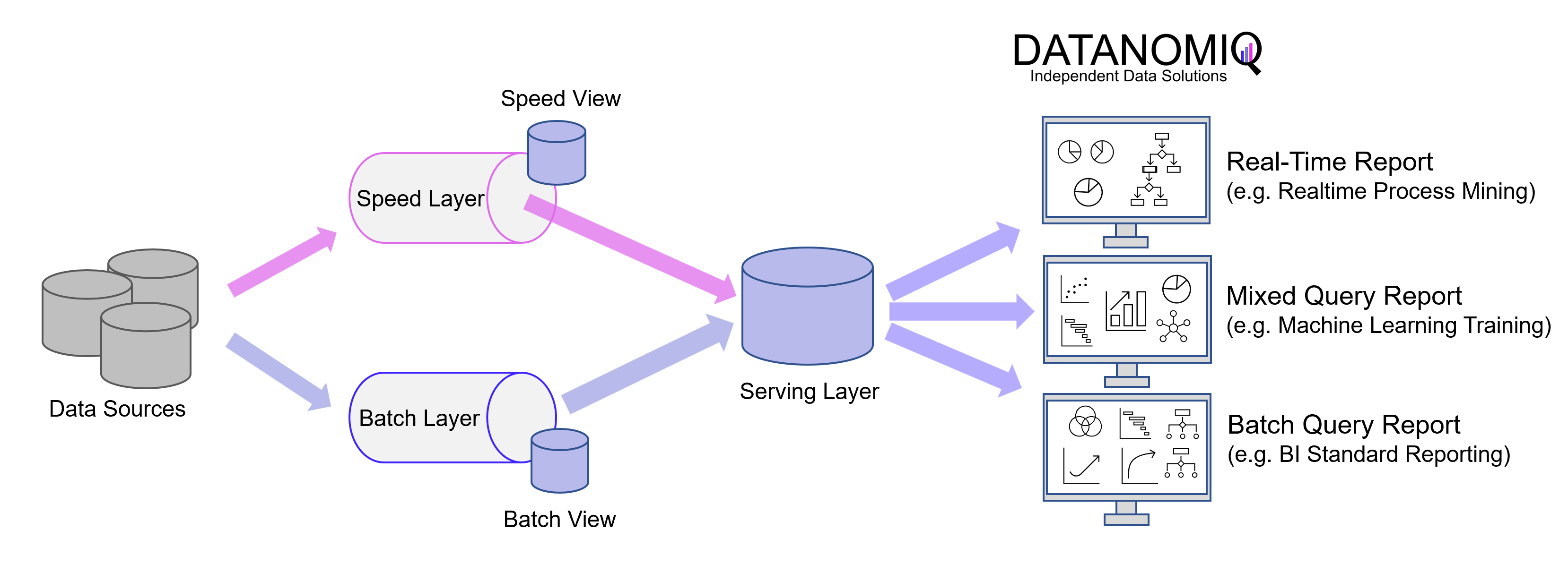
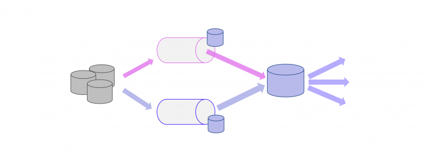
Here is a simplified depiction of the Lambda architecture, showcasing the multi-store concept and the serving layer. In this representation, there is a separate store for events within the speed layer and another store for data loaded during batch processing. The serving layer acts as a mediator, enabling subsequent applications to access the data. It is important to note that in the Lambda architecture, the serving layer can be omitted, allowing batch processing and event streaming to remain separate entities.
The batch views within the Lambda architecture allow for the application of more complex or resource-intensive rules, resulting in superior data quality and reduced bias over time. On the other hand, the real-time views provide immediate access to the most current data.
The Serving Layer serves as a conduit for various data queries originating from both the batch and speed layers. It receives batch views from the batch layer and near-real-time views from the speed layer, utilizing this data to facilitate standard reporting and ad hoc analytics.
The Lambda architecture effectively balances speed, reliability, and scalability. However, it is worth mentioning that while the batch layer and real-time stream handle different scenarios, their underlying processing logic often shares similarities. As a result, the development and maintenance efforts for both layers should not be underestimated.
Kappa – Architecture
Jay Kreps introduced the Kappa architecture in 2014 as an alternative to the Lambda architecture. It addresses the redundancy present in the Lambda architecture by completely removing the batch component. By eliminating the parallel operation of two pipelines, the Kappa architecture simplifies the overall architectural complexity.
In the Kappa architecture, only the speed layer, represented by an event-based streaming pipeline, remains. The fundamental concept is to handle real-time data processing and continuous data reprocessing using a single stream processing engine. This approach allows for the avoidance of a multi-layer lambda architecture while ensuring the quality of data processing is maintained.
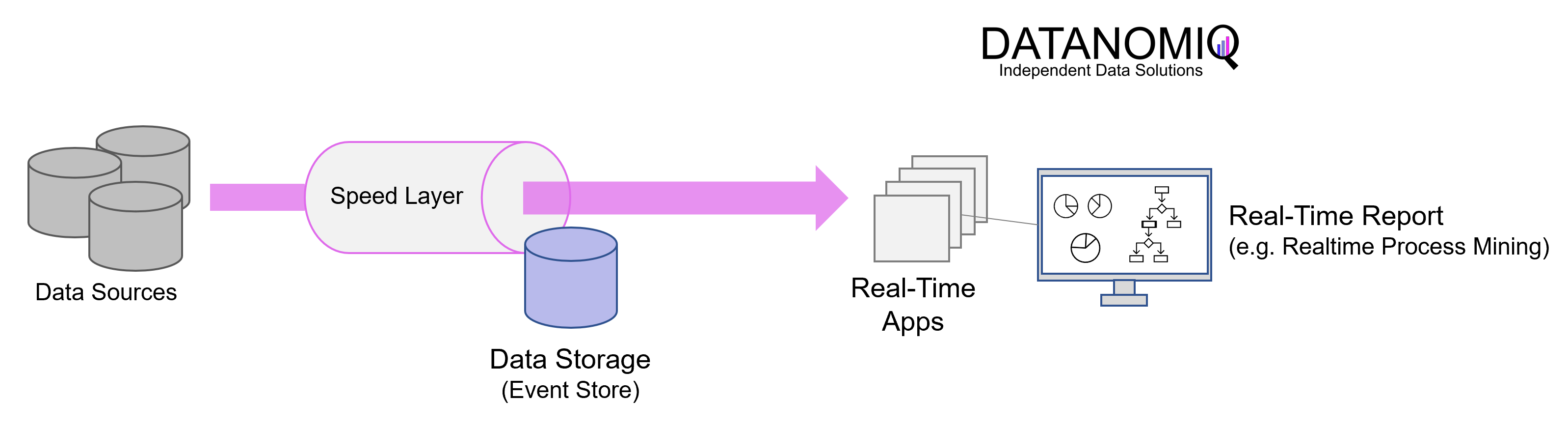
Illustrated simplified Kappa Architecture. This architectural concept relies on event streaming as the core element of data delivery.
In practical implementation, the Kappa architecture is commonly deployed using Apache Kafka or Kafka-based tools. Applications can directly read from and write to Kafka or an alternative message queue tool. For existing event sources, listeners are utilized to stream writes directly from database logs or similar data stores. This approach eliminates the need for inbound batch processing and reduces resource requirements.
By treating every data point as a streaming event, the Kappa architecture enables the ability to near-realtime analytics and observe the state of all data in the organization at any given point. Queries can be performed at a single location, eliminating the need to compare batch and velocity views.
However, there are challenges associated with this architecture. Data processing must be done as a data stream, leading to difficulties such as managing duplicate events, cross-referencing events, and maintaining correct operation order. While batch processing can handle retrospective consolidation of multiple data sets, these challenges persist in the Kappa architecture. As a result, implementing architectures based on the Kappa concept can be more complex compared to those based on the Lambda concept, even though the latter may appear clearer in architectural sketches.
The Kappa architecture is particularly suitable when event streaming or real-time processing use cases are predominant. It offers the advantage of having a single ETL platform to develop and maintain. It is well-suited for developing data systems that emphasize online learning and do not require a separate batch layer. The sequence of events and queries is not predefined but generated in later steps based on business logic, prioritizing speed.
Use cases – When to use which architecture?
It is important to note that Kappa architecture does not serve as a direct substitute for Lambda architecture, as there are certain use cases supported by Lambda that cannot be seamlessly migrated. The Lambda architecture is better suited for implementing complex data processes and ensuring consistently complete data provisioning compared to the pure event processing approach of Kappa. As a result, many Data Lakehouse systems are built upon the foundations of the Lambda architecture.
Requirements that clearly speak for Lambda
- If data is to be processed ad-hoc on quasi unchanging, quality-assured databases, or if the focus of the database is on data quality and the avoidance of inconsistencies.
- When fast responses are required, but the system must be able to handle different update cycles.
Requirements that clearly speak in favor of Kappa:
- When the algorithms applied to the real-time data and the historical data are identical.
- If the analytics system is online learning capable and therefore does not require a batch layer.
- The order of events and queries does not matter, but the stream processing platforms can exchange data with the database instantly at any time.
If your requirements prioritize a highly reliable Data Lakehouse update process and efficient machine learning model training for accurate event predictions, the Lambda architecture is the recommended choice. By leveraging both the batch layer and the speed layer, the Lambda architecture ensures minimal errors and optimized processing speed.
Alternatively, if you seek a streamlined Big Data architecture that excels in handling distinct and continuously emerging events (e.g., fueling data for numerous mobile applications), the Kappa architecture is the ideal solution for data platforms with the main purpose of real-time data processing. Its focus on unique, ongoing events allows for effective and responsive data processing.